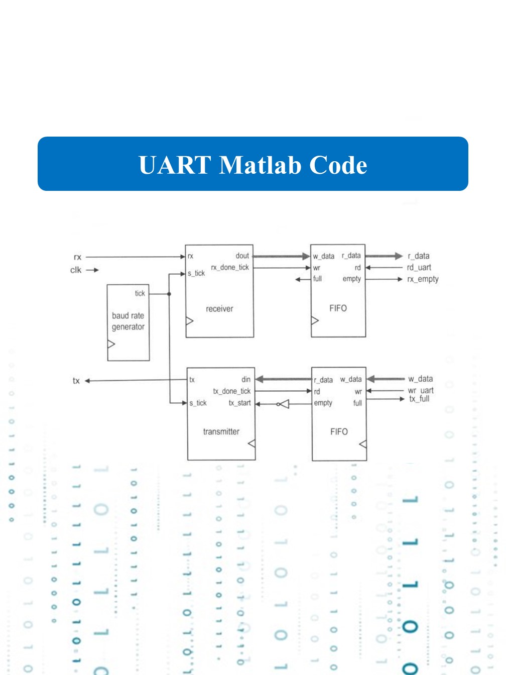
UART Code
UART Code
UART (Universal Asynchronous Receiver-Transmitter) is a serial communication protocol widely used in embedded systems for short-distance, low-speed, and reliable data exchange. Unlike protocols like SPI or I2C, UART is asynchronous,
meaning there is no shared clock between the sender and receiver. Here’s a detailed breakdown of how UART works and its key concepts:
1. UART Overview:
UART is a hardware communication module typically built into microcontrollers that facilitates full-duplex communication (transmitting and receiving data simultaneously). Data is sent in the form of bits, one after another (serially),
over a single line (TX for transmission, RX for reception).
2. How UART Works:
Data Format: UART transmits data in the form of packets.
A typical UART data frame consists of:
Start Bit (1 bit): Always low (logic 0). It indicates the beginning of data transmission.
Data Bits (5-9 bits): These bits represent the actual data. Common configurations use 8 data bits.
Parity Bit (Optional, 1 bit): Used for error-checking. It can be even parity, odd parity, or none.
Stop Bit (1 or 2 bits): Always high (logic 1). It indicates the end of data transmission.
Example Frame (8N1 format):
| Start | Data Bits (8) | Stop |
| 0 | d0-d7 | 1 |
Baud Rate: The baud rate defines the speed of communication, expressed in bits per second (bps). Common baud rates include 9600, 115200, etc. Both devices must be configured with the same baud rate for successful communication.
Transmission: UART transmits data asynchronously. The transmitter sends data byte by byte, including the start bit, data bits, parity (if any), and stop bit. Each byte is framed and sent one after another.
Reception: The receiver continuously listens for the start bit. Upon detecting it, the receiver reads the data bits and checks for any errors using the parity bit (if enabled). Finally, the stop bit confirms the end of the frame.
3. UART Communication:
Simplex, Half-Duplex, and Full-Duplex Modes:
Simplex: Data flows in one direction only (TX to RX).
Half-Duplex: Data flows in both directions, but not simultaneously.
Full-Duplex: Data flows in both directions simultaneously
Signal Lines:
TX (Transmitter): Carries outgoing data.
RX (Receiver): Carries incoming data.
Some UART setups also involve additional control lines like RTS (Request to Send) and CTS (Clear to Send) for hardware flow control, but basic UART only needs TX and RX.
4. UART Error Handling:
Common errors include:
Framing Error: Occurs if the stop bit is not detected where expected.
Parity Error: Happens when the received data’s parity doesn’t match the expected parity.
Overrun Error: Occurs when the receiver’s buffer is full, and more data is incoming.
5. Advantages of UART:
Simple and cost-effective for short-distance communication.
No need for a clock signal, reducing the number of required lines.
Widely supported and easy to implement.
6. Disadvantages of UART:
Limited speed compared to other protocols like SPI or I2C.
Only supports point-to-point communication (one sender and one receiver).
Requires both devices to use the same baud rate for reliable communication.
7. Applications of UART:
Debugging and console interfaces (e.g., connecting to a terminal).
Communication between microcontrollers and modules like GPS, Bluetooth, or GSM.
Data logging systems and PC communication.
